♦ This article was originally published in Pushing the Envelope newsletter, Spring 2020.


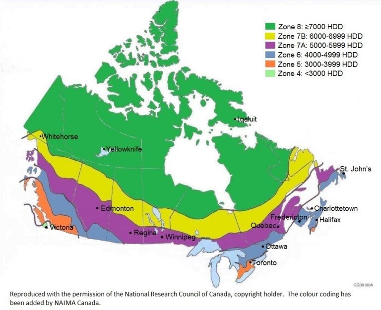
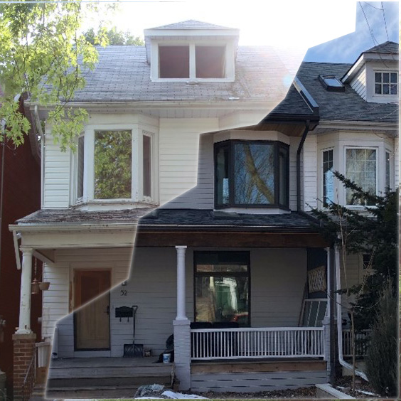
The journey in pursuing my own hands-on approach to complete a deep energy retrofit (DER) began in 2014 when I purchased a 1904 semi-detached home in the east end of Toronto (Photo 1). My formal educational is in civil engineering, but my real passion is building science; so, what better way to learn than to get my hands dirty on my own self-build?
Our first winter of 2014-2015 proved the home’s major energy inefficiencies. It was incredibly cold and drafty. The HVAC ducts ran through the unconditioned crawlspace and were neither insulated nor air sealed, and a large hole poked through the foundation wall for building “fresh air”; walls were largely uninsulated. All aspects that made the house perfect for a DER.
Project goals
Like any high-performance build should aim to achieve, the goal was to improve the:
- Buildings durability;
- Occupant comfort;
- Occupant health; and,
- Buildings energy efficiencies.
The philosophy was to improve the building using principals from the “pretty good house” movement. I followed the exterior insulation method outlined in the “Mass Save Deep Energy Retrofit Builder Guide” by Building Science Corp. (figure 1), and the forum discussions at www.GreenBuildingAdvisor.com.

Other goals included working through smart efficient details in order to better understand the constructability of high-performance systems and materials, building an architecturally aspiring green home (what’s the point of a high-performance house if its an ugly box, destined to the landfill within a few decades), and maximizing passive heating and passive cooling systems. At the time, going off fossil fuels was not a goal (however, today it most certainly would be); and neither was attaining a high energy certification target such as Passive House.
Performance highlights
As this article title suggests, super insulation was amongst one of the main performance focuses. An overview of the projects thermal insulative performance is shown in Figure 2, and compared against code-built project and the original project prior to the deep energy retrofit. The figure also highlights how windows de-rate the effective R-value of walls, even with high-performance windows and a 20 per cent window to wall ratio.

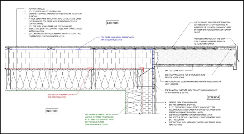
High performance was achieved with continuous exterior insulation and batt insulation within the stud cavities. To provide an uninterrupted blanket of continuous insulation, the existing roof overhands were cut off with the chainsaw approach (figure 1). Thereafter new eave overhangs were installed for good water control and maintain architectural intent (figure 3). New, high-performing windows were installed to maximize overall building performance.
Insulation systems
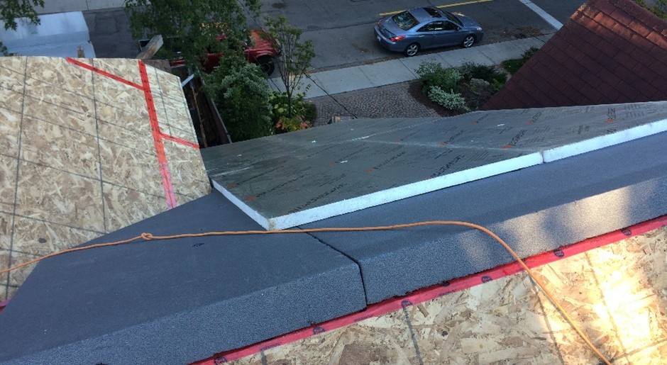
Four-inch thick exterior insulation in two staggered lifts of expanded polystyrene (EPS) foam board and graphite impregnated EPS (GPS or Neopor® by BASF) wrapped the exterior walls, and seven-inch thick with the same insulations wrapped the warm roof (photo 2). 1×3 pine strapping was provided on the walls and roof to allow the attachment of siding and roofing, while providing a vented rainscreen cavity. Long screws were provided to secure the strapping back to the framing at the walls and roof. Figure 3 details the wall to roof interface showcasing the continuous control layers (vapour, air, thermal, water).

I chose EPS and GPS foam board insulations based on good insulative properties, lower costs, and lower global warming blowing agent potential (figure 4); and mineral wool batt insulation to fill the walls and ceilings due to its excellent fire proofing, sound deadening, and insulation properties.
Spray foam insulation was decided against based on its very high global warming blowing agent potential, toxicity, and flammability. There are also concerns with its long-term air tightness (one of its primary benefits). I generally caution its use when used as an air barrier.

Sheep’s wool is a great natural product with green benefits and a good indoor air quality contributor, but was found to have a relatively high embodied energy (the sheered wool came from Ireland, fabricated into batts in central Europe). High material costs also played a part.
Blown in cellulose is a great product but less of a DIY installation, and typically requires the structure to be insulated at one time (where batts can be installed in phases). Cellulose is a sound insulation product and I would have no issues recommending this insulation system.
Exterior insulation finish system (EIFS) can be an excellent system when installed correctly but was ultimately discounted because of its requirements for professional installation and its architectural style. This is also another sound insulation product.
Air barrier and vapour retarder
The traditional poly vapour barrier was designed out to prevent the risks associated with a vapour sandwich, caused by the vapour impermeable poly sheet on the interior and foil faced EPS on the exterior. These two impermeable surfaces could trap moisture within the wall. If not allowed to dry, trapped moisture could lead to building failure. Moisture could enter from the interior in the form of water vapour through an electrical receptacle, or from liquid water penetration around a window. It’s a factor of when, not if there will be moisture penetration.
The buildings vapour retarder was provided by latex paint on drywall using the airtight drywall approach (this method is incredibly tricky to do correctly and should only be completed by experienced professionals); an acceptable method by the Ontario Building Code. A smart vapour retarder (a membrane that changes its vapour permeability based on moisture content) was utilized in the bathrooms. Although a robust design, an even more resilient design would have been to drop the foil facer on the exterior and provide a smart vapour retarder on the interior behind a service cavity; out of harms reach of electrical, plumbing, and other service penetrations.
At the building’s rear extension and over the roof structure, the air barrier was OSB sheathing with taped seams (figure 3). Elsewhere however, the air barrier (and water control layer), was provided by the foil faced taped insulation seams. It’s best to provide the air barrier towards the building interior as was done for the rear extension. The air barrier could also double as your vapour retarder if installed correctly. Red tuck tape was used to tape the foil faced insulation (photo 2). Although this tape seemed to be an effective low-cost solution at the time (and routinely used on construction projects throughout), it later was found to debond indiscriminately on the roof and walls to the foil facer. Where observed, the tape was substituted with a high quality acrylic adhesive tape with outstanding results. I guess you get for what you pay for.
Windows
The windows were high performance triple glazed, double low-e coated, fiberglass framed windows. To deal with the thicker walls, factory installed interior jamb extensions were fitted to allow the windows to be pushed out of the framing to align with the exterior insulation plane to maximize thermal performance (figure 5). Low-e coating type and glazing surface were customized on each window elevation to maximize solar heat gain in the winter and minimize in the summer.

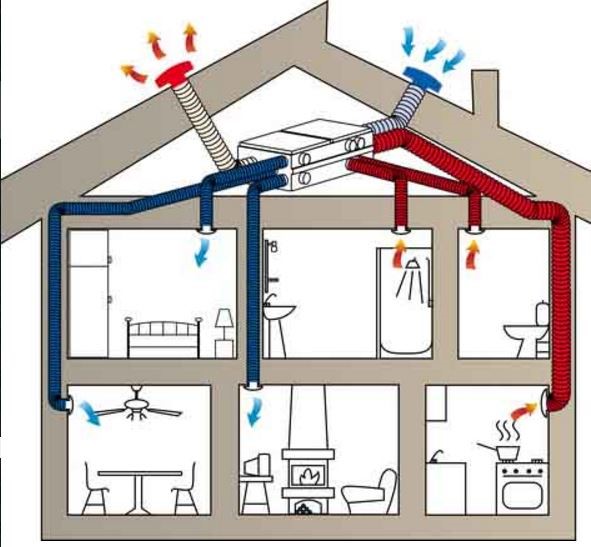
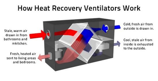
Mechanical HVAC systems
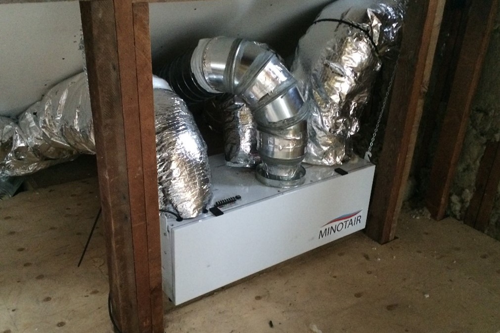
High performance heat recovery ventilators (HRV’s) are critical for high performance, air-tight buildings; they are the lungs of the building. The HVAC systems, or as I like to refer to them as the comfort systems, comprises of a combined HRV and heat pump (HP) system. This specialized all-in-one unit provides fresh air with HEPA filtration, heating, cooling, and dehumidification; operating based on sensors of temperature and humidity. The unit (manufactured by Minotair), with a coefficient of performance (COP) of four, lives in the conditioned knee wall to optimize space (photo 3). For future builds, I would prefer a standalone HRV and HP, as each system has its own job. These combined systems could be reserved for very small buildings such as multi-unit residential units.
A mid efficiency (67 per cent) gas fireplace was selected for supplemental heat and ambience. It provides a resilient heat source that operates without electricity (during power outage), and is sized to heat the entire house in winter if need be. The fireplace incorporates a direct, co-axial vent to draw and preheat combustion air from the exterior. This provides three benefits – sustains an air-tight building assembly; maintains a pressure equalized space, so not to draw in uncontrolled and unconditioned exterior air; and improves efficiency.
A high efficiency (95 per cent) direct vent condensing tankless gas water heater provides hot water. While these gas units are very efficient, there has been large leaps in electric driven hot water technologies over the past decade. HP water heaters have extremely high COP levels, with one manufacturer (Sanden) having a published COP of 6.
Closing
While this build did not pursue any high-performance certifications, it certainly entailed a lot of high-performance systems, and is leaps ahead of the standard code minimum build. The hands-on experience taught me many lessons. For me, the project was a success both in performance and architectural aesthetics (photo 4). For others pursuing a high-performance project, the teams experience and collaboration will be most critical for the success and cost of the build.